


|
| electron Tube Data sheets |
|
|
| ||
|
| My Absurd EL51 Amplifier |
 |
2025-05-06 The potmeters used were of poor mechanical quality. I was happy to find some nos all metal ones. Latest version of the circuit diagram: Circuit diagram 'Franks Absurd EL51 Amplifier' |
 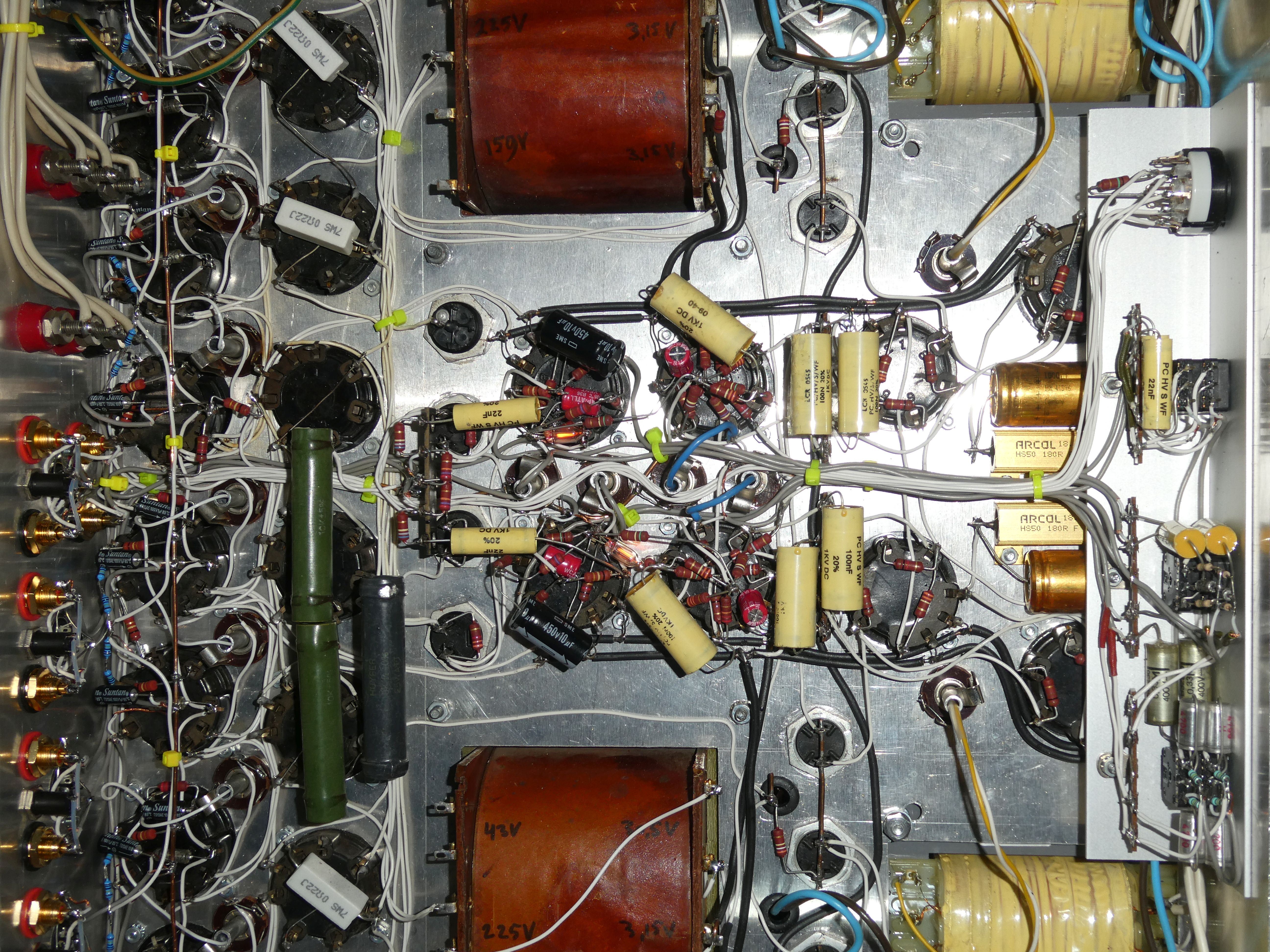 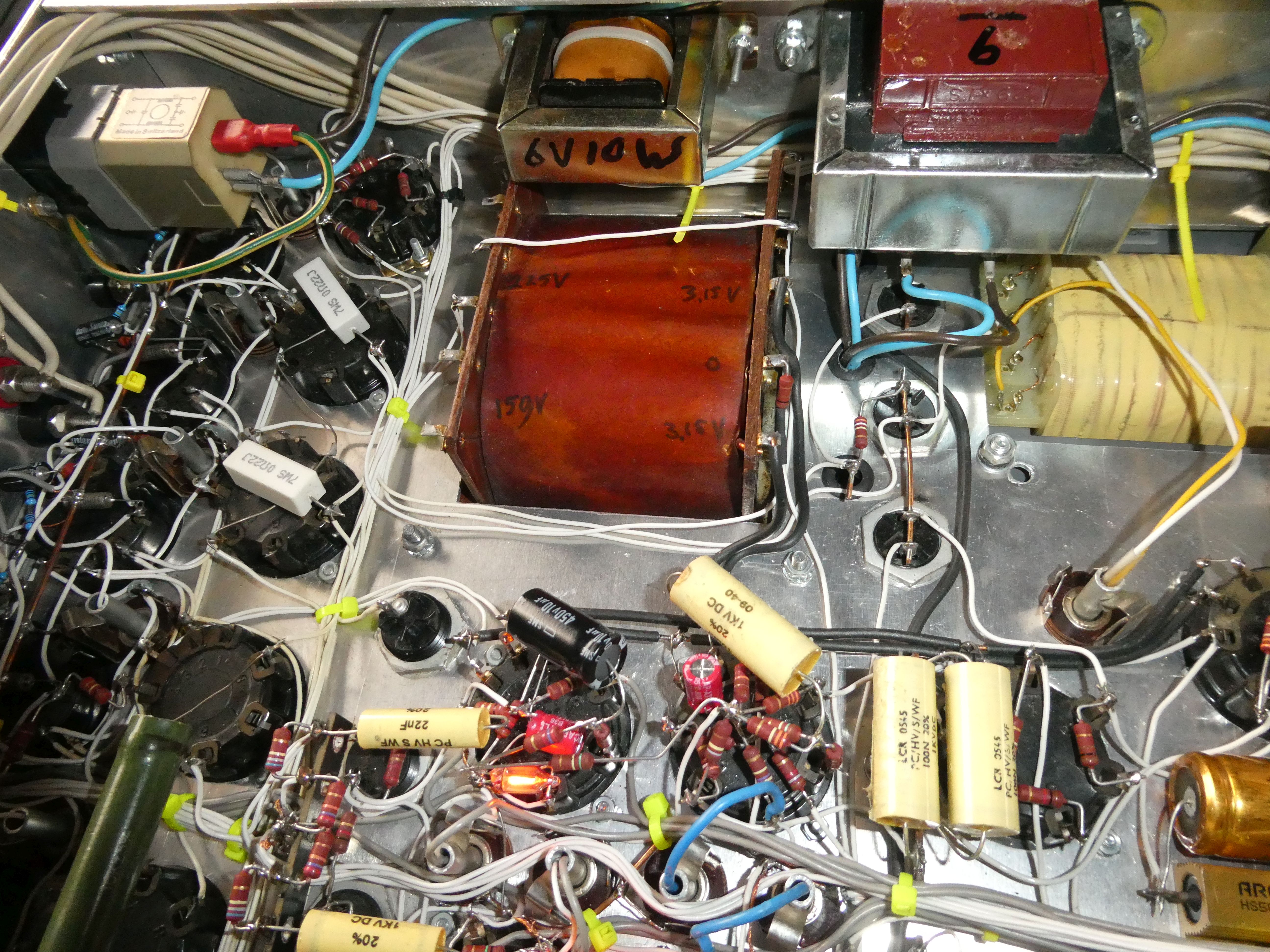 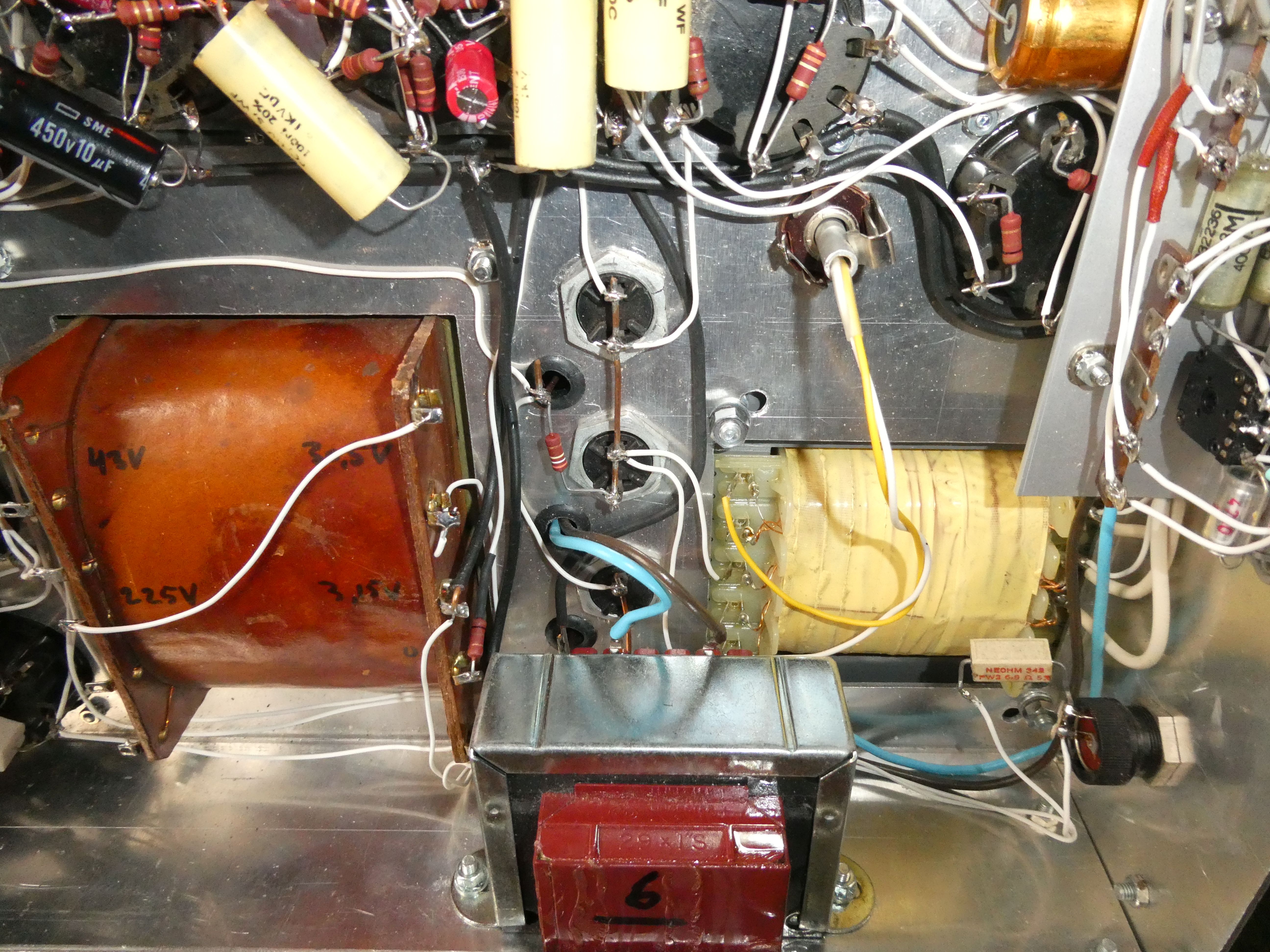 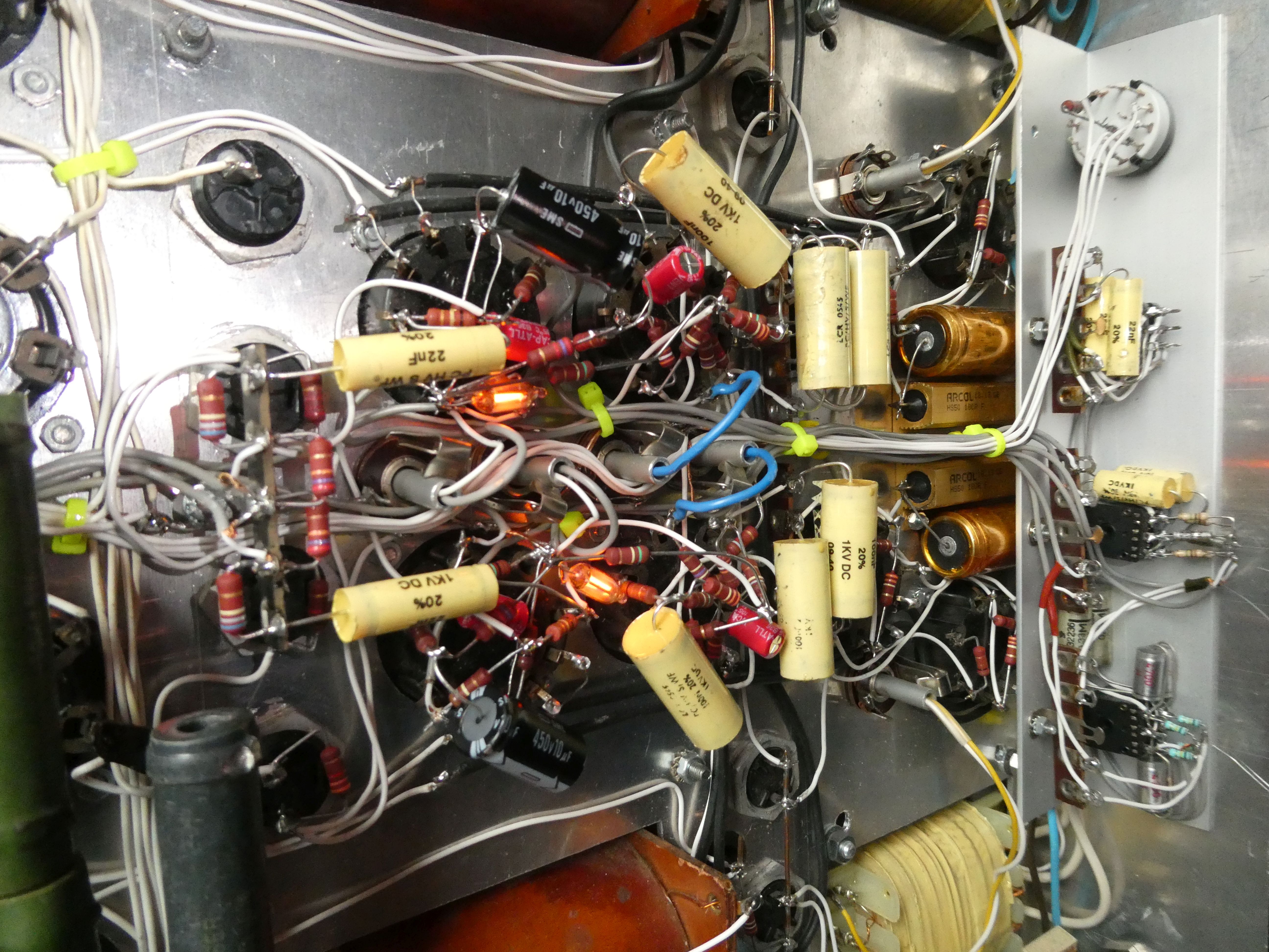 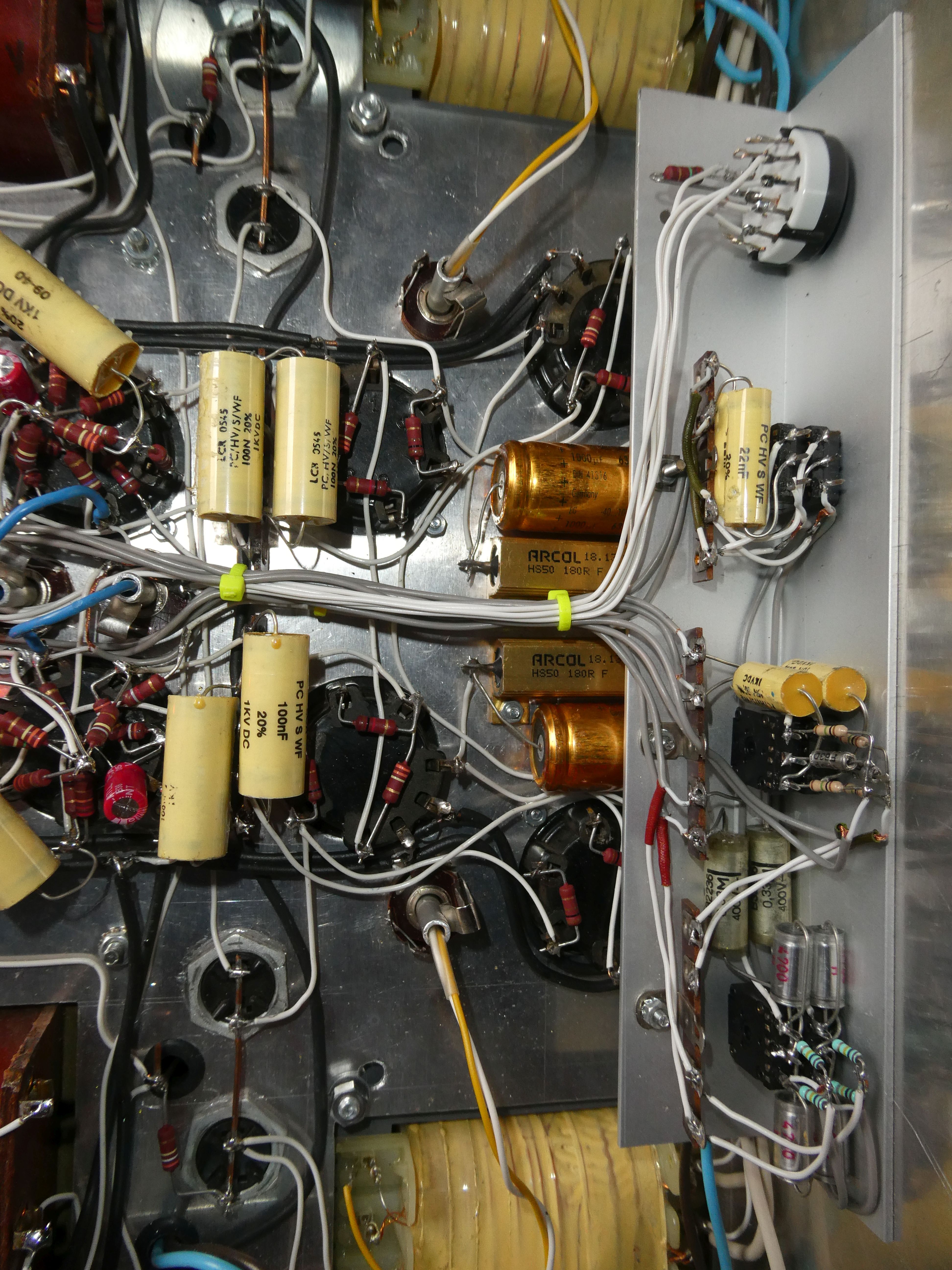   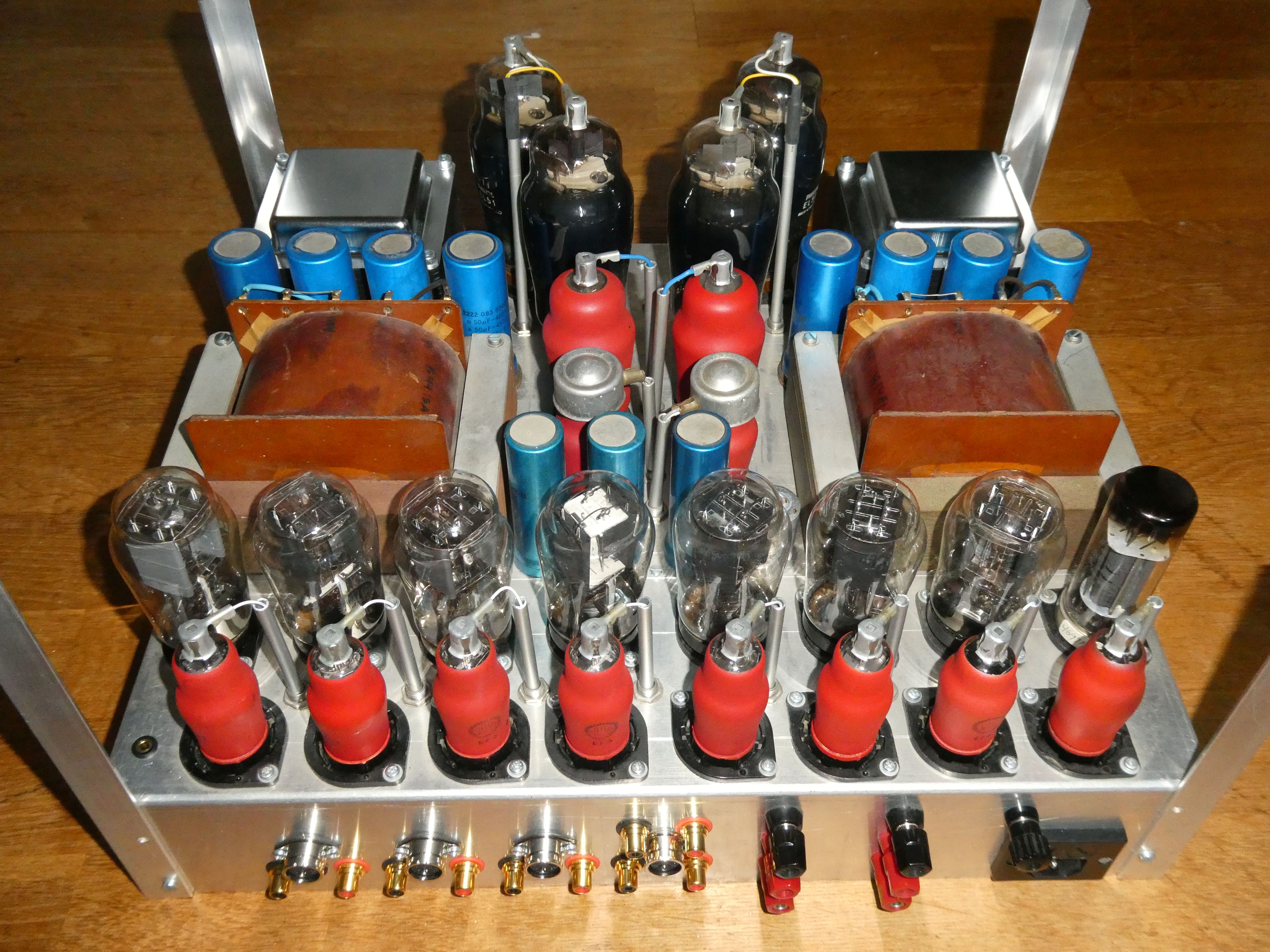    |
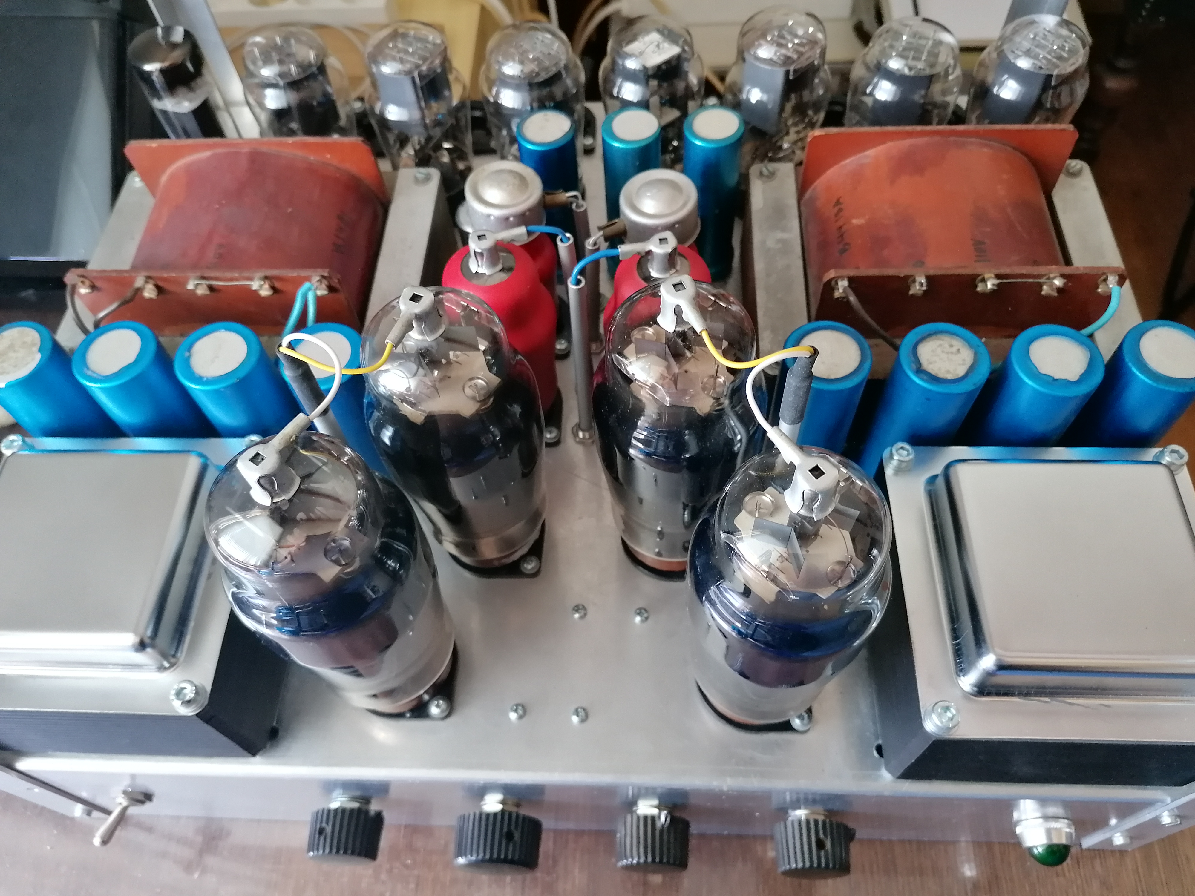
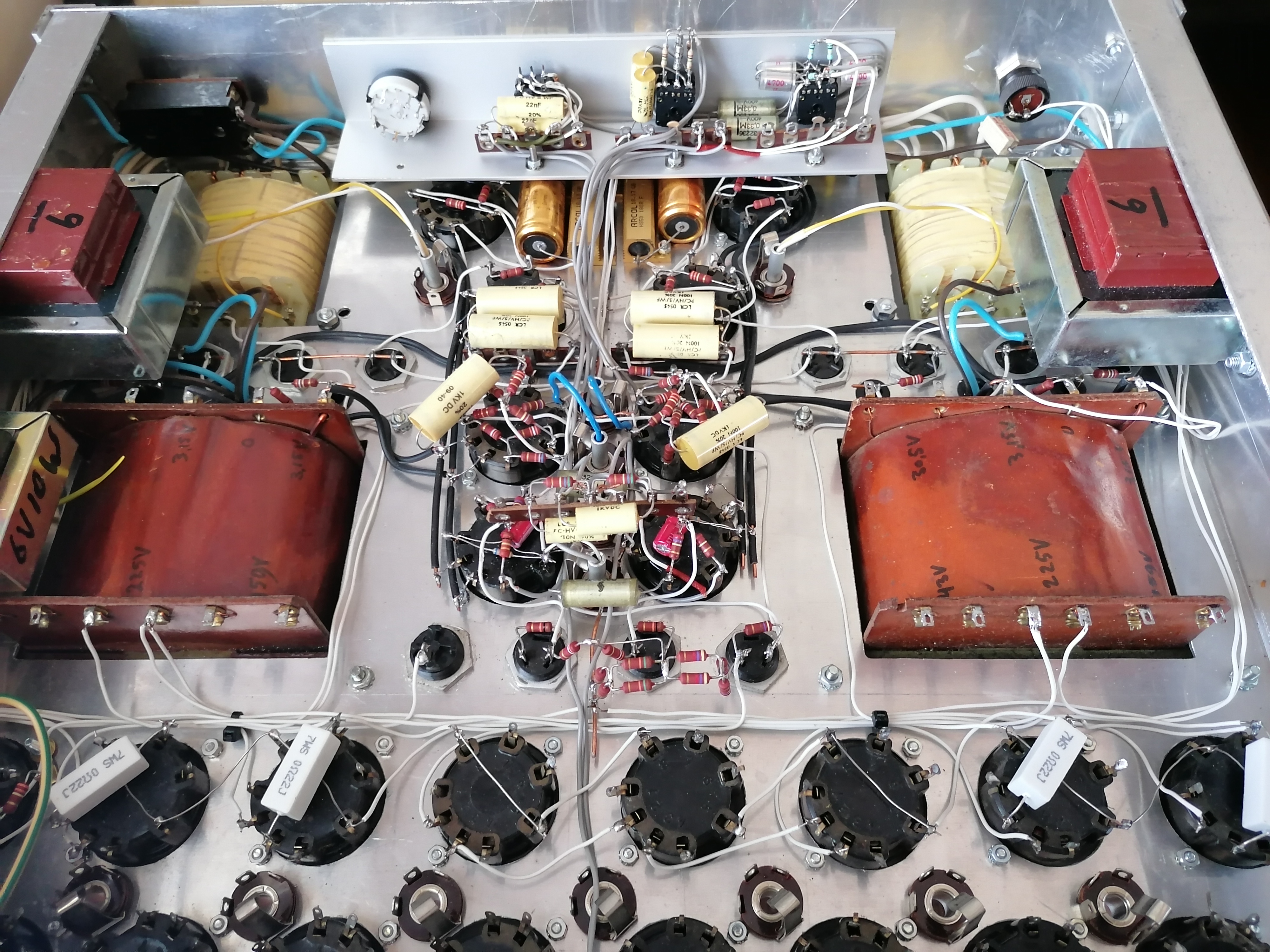
2025-01-30 The amplifier works fine now. I started this amplifier design early 2006 with some idea's. I also had some rules: Rule 1: Only use tubes with P-base. Rule 2: Use an EE1 or EEP1 as phase inverter and use EL51's as output tubes. Rule 3: It must fit en an 19" cabinet that I have. Rule 4: Use circuits that you don't see often or never. Only once I have seen this tone control circuit. I have never seen this input selection circuit. The solderwork may look a bit strange here and there. That is because I designed the amplifier while building it and I did a lot of experimenting. I had a lot of problems with the tone control circuit (ECH4). I could not get it stable. From time to time there was some oscillation with a very low frequency. Also some ECH4's had more problems with that than others. I noticed it had something to do with the g2,g4 pin. So when I finally made a low impedance at the g2,g4 pin using a neon lamp, the problem was gone. If you like you can check out the circuit diagram. I drew it from the amplifier afterwards, not before I built it. Hope you can read it. If you use any of it... I am not responsible for anyting. Take care, it uses lethal voltages. [See later posts for the circuit diagram] Note: The amplifier uses 420 Watts with volume at 0. I used a higher cathode resistor for the EL51's to reduce power otherwise it would be even more. So it is not very milieu friendly. frank |
  |
2024-08-25 Also this year I did some stuff work on the EL51 amp. I found an old schematic for tonecontrol which I wanted to try. The ECH4 is used for this. Heptode with g3 is 0V is input tube. The Triode is used for active control. The output (at 100k resistor) goes to the volume control potmeter and then to the EEP1 phase converter. 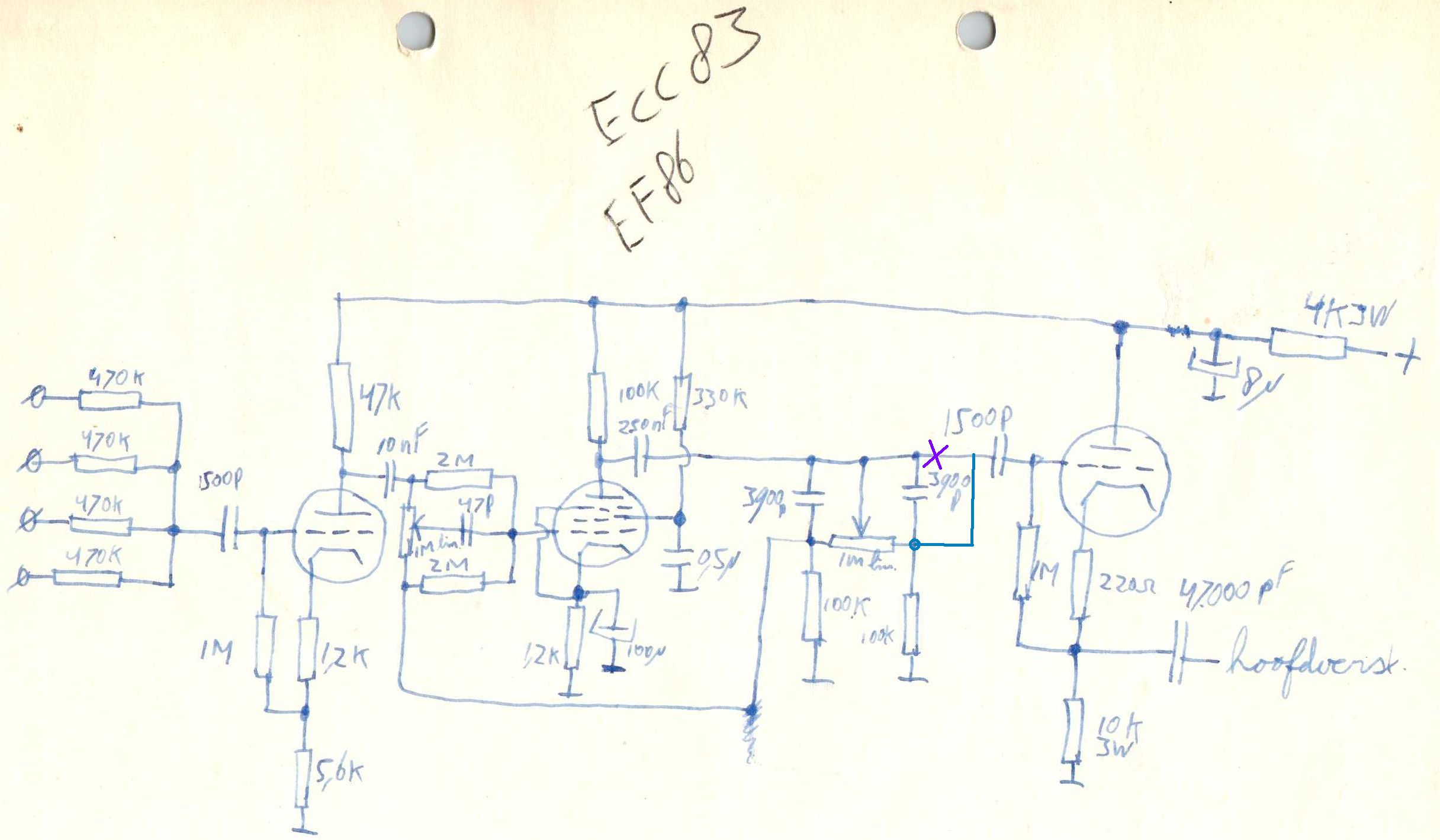 It works quite well. Though the ECH4 is microphonic and the 50Hz from te filament is a problem. That is why I placed the volume potmeter between the ECH4 tone control circuits and the EEP1. It is still humming a little bit by the output stage. Needs work or maybe I leave it. |
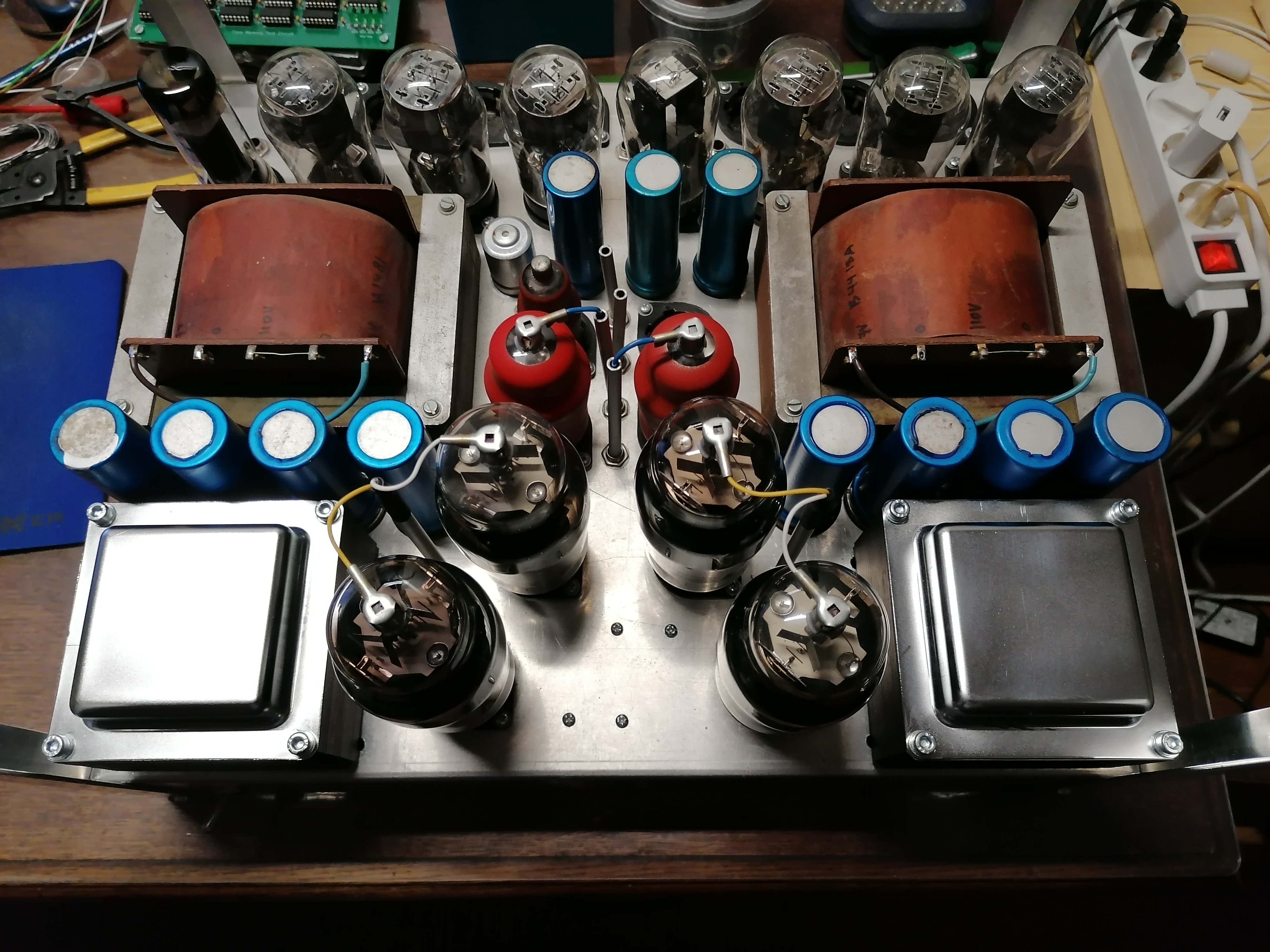  |
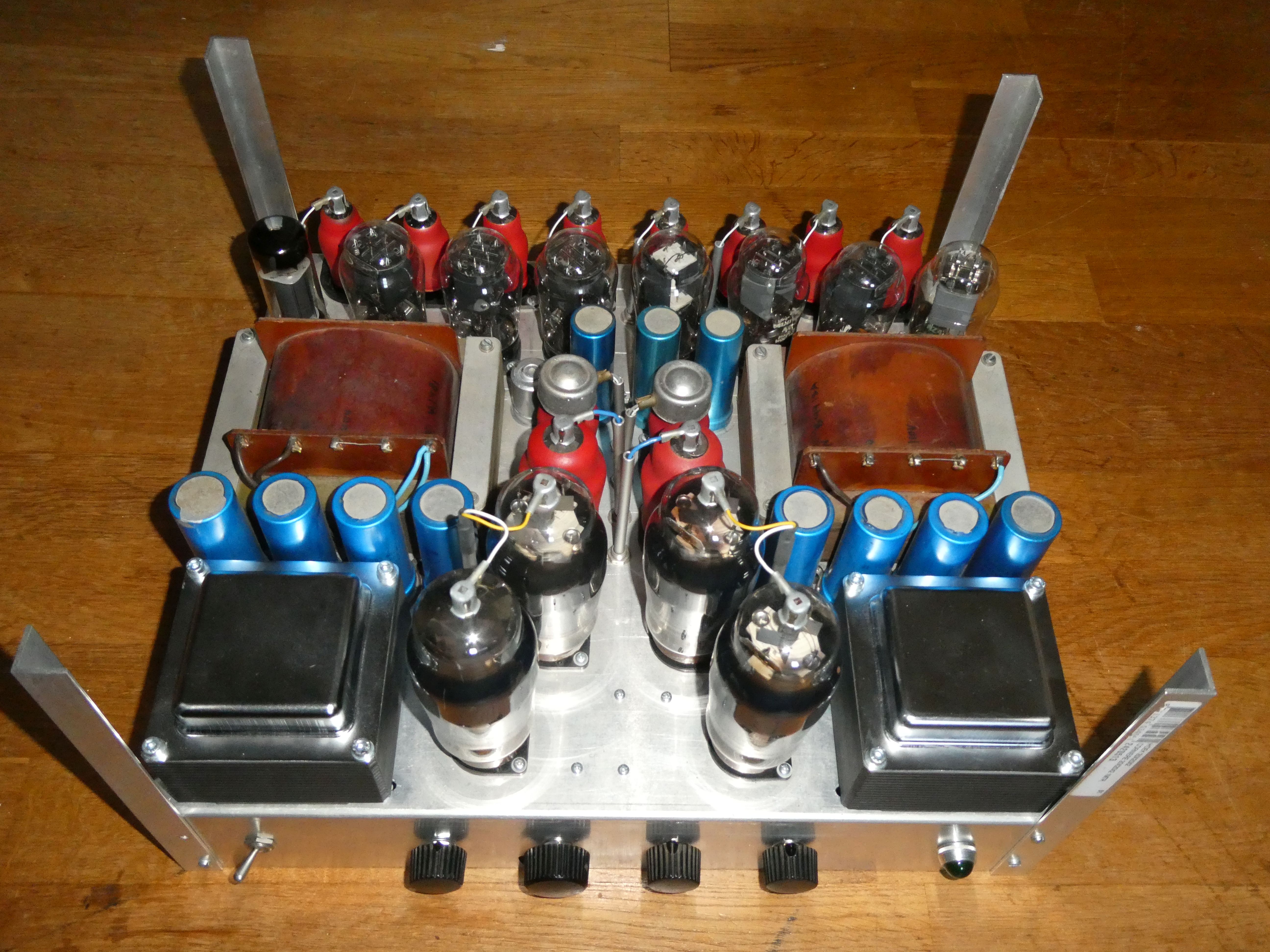
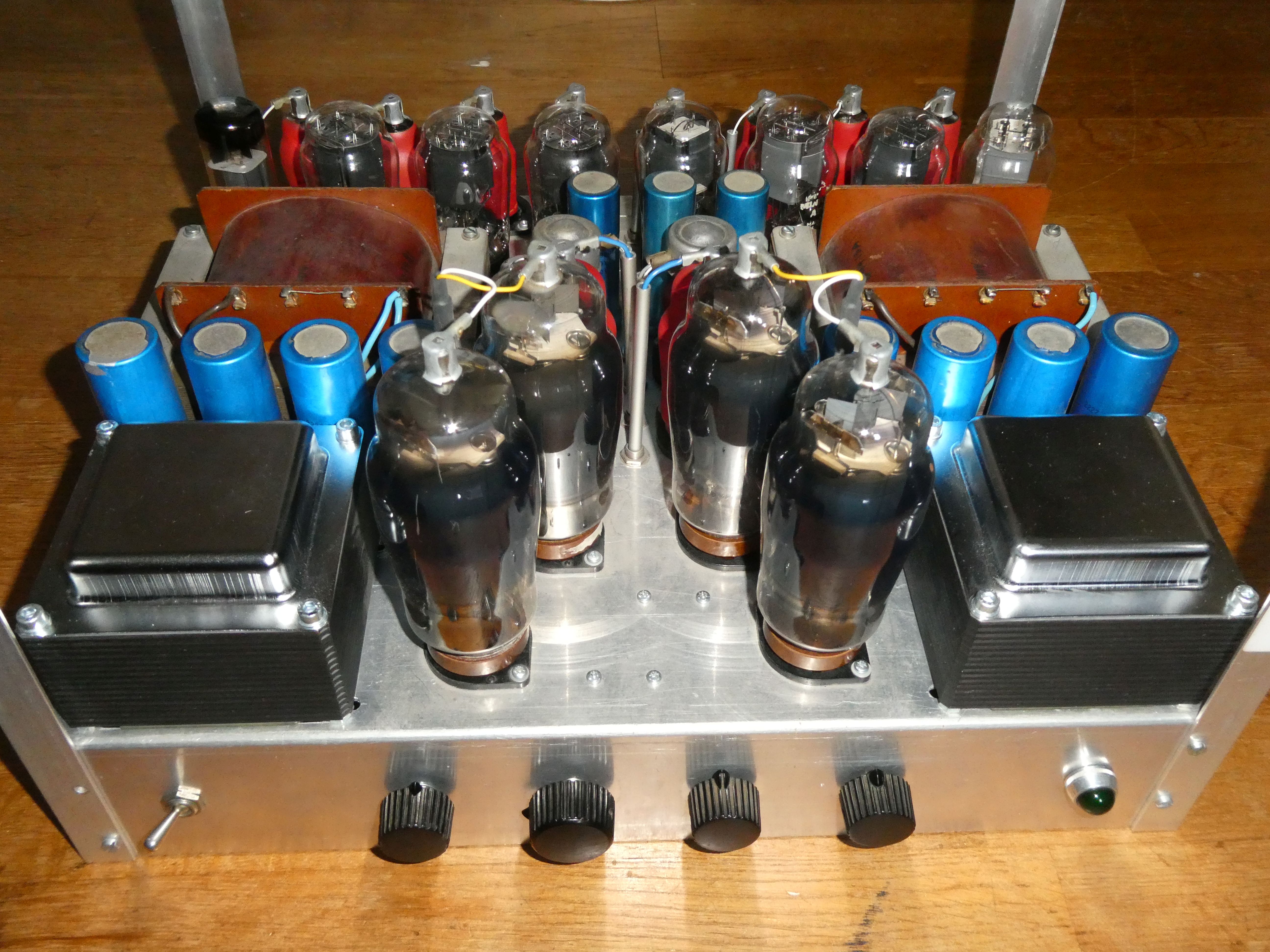
2021-05-10 I decided to do something again ... Maybe finish it this year :) One output stage is built and i'm tuning the circuit. I added a 4699 tube to reduce ripple voltage on the driverstage. The output transformers are replaced with 5k Raa types. |
  |
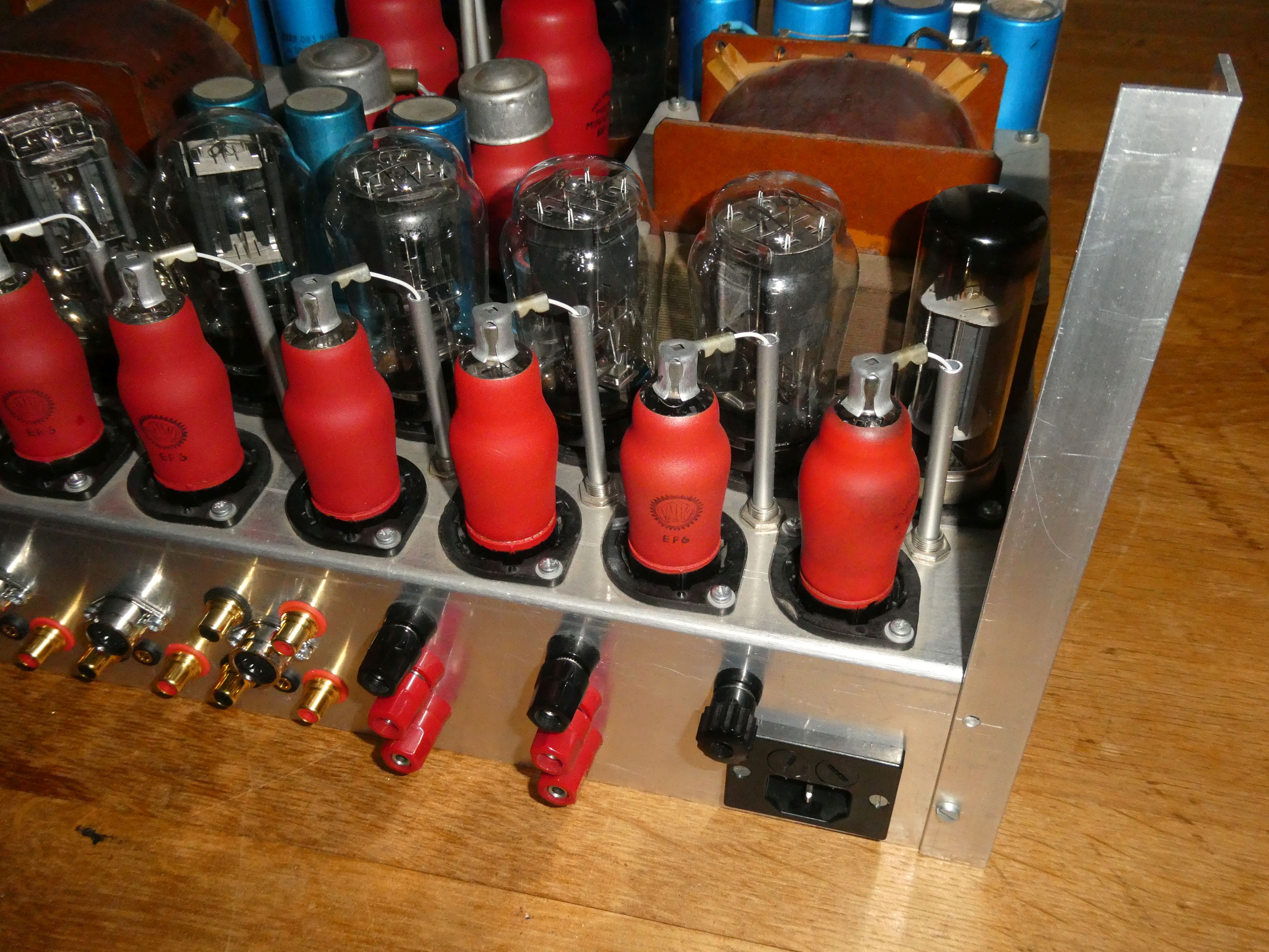
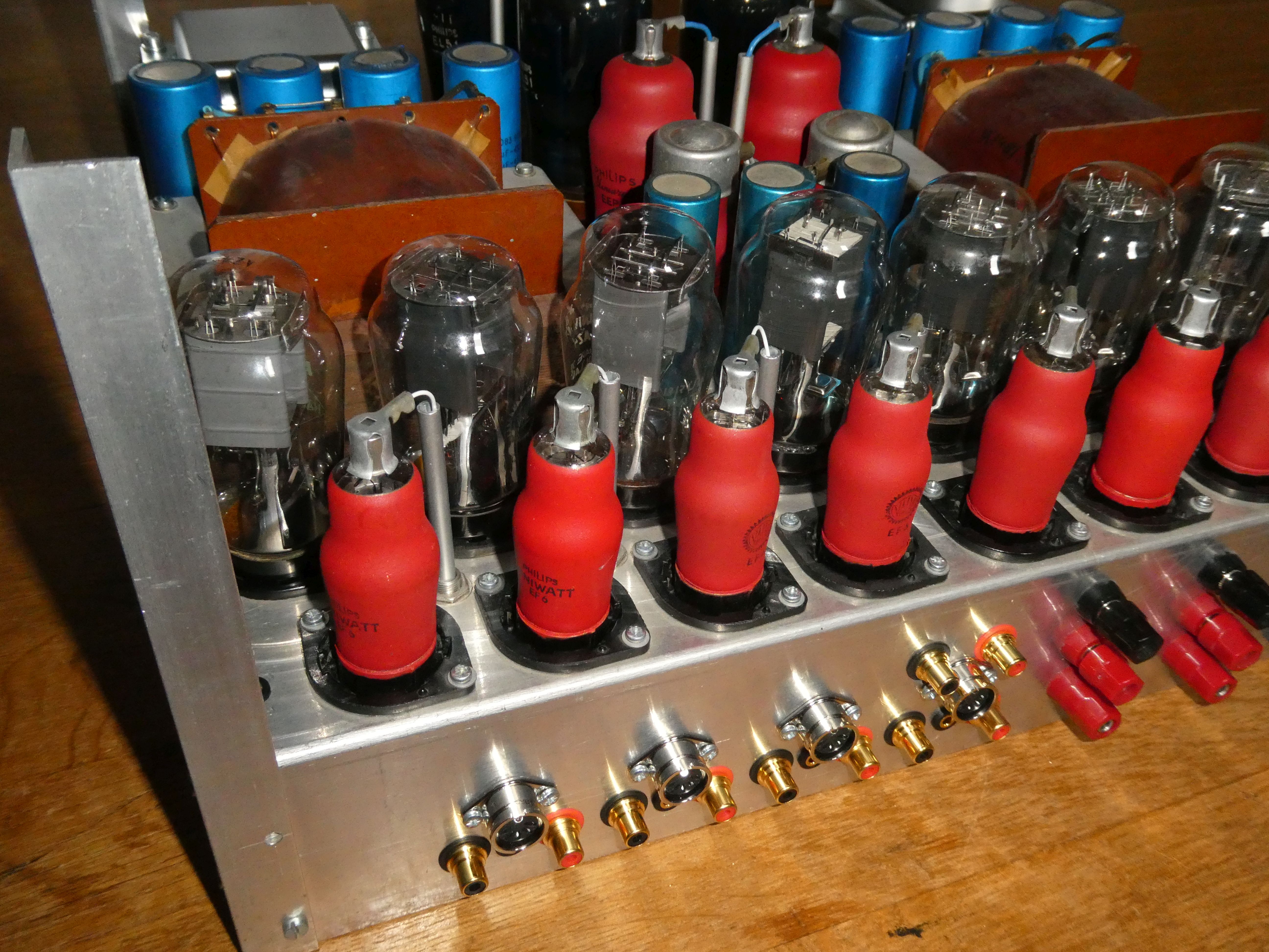
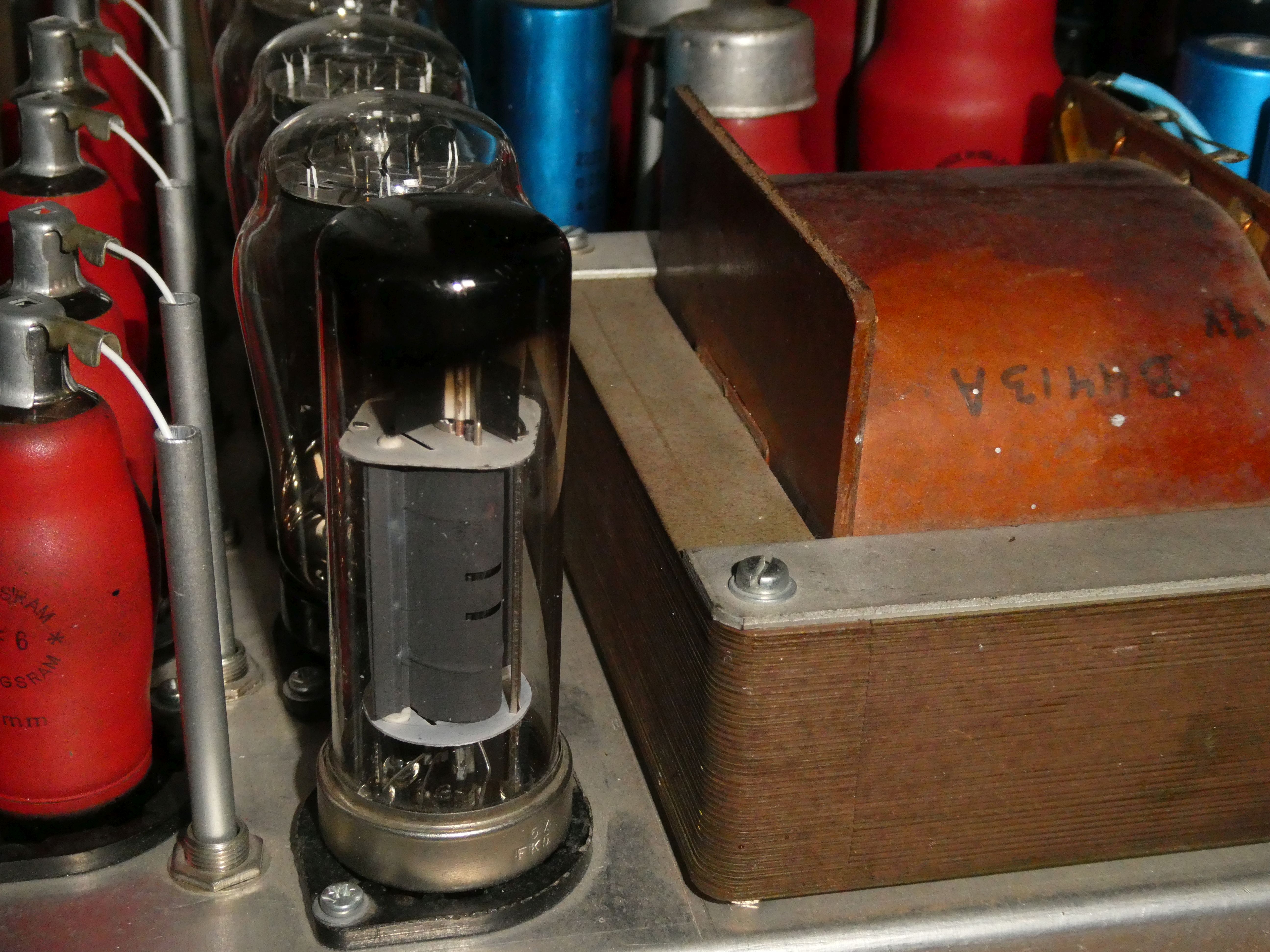
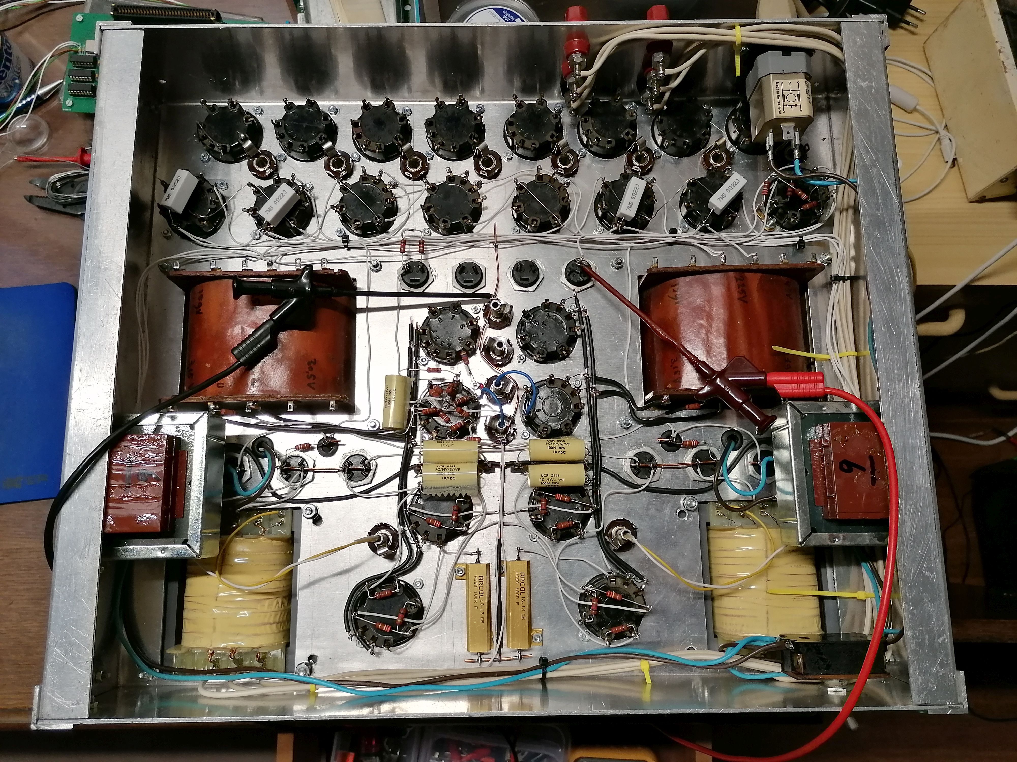
2011-07-28 Here you can see that I made some aluminum pipes for the wires to the top connections of the tubes. It took a while to find a good solution. Glue was not working so I had to find something else. A friend of me suggested using a jack plug socket which is 6.35 mm while the aluminum pipe is 6mm. So they skew a bit but that is ok for me. Most mechanical work has been done so now I can add some electronic stuff. |
 |
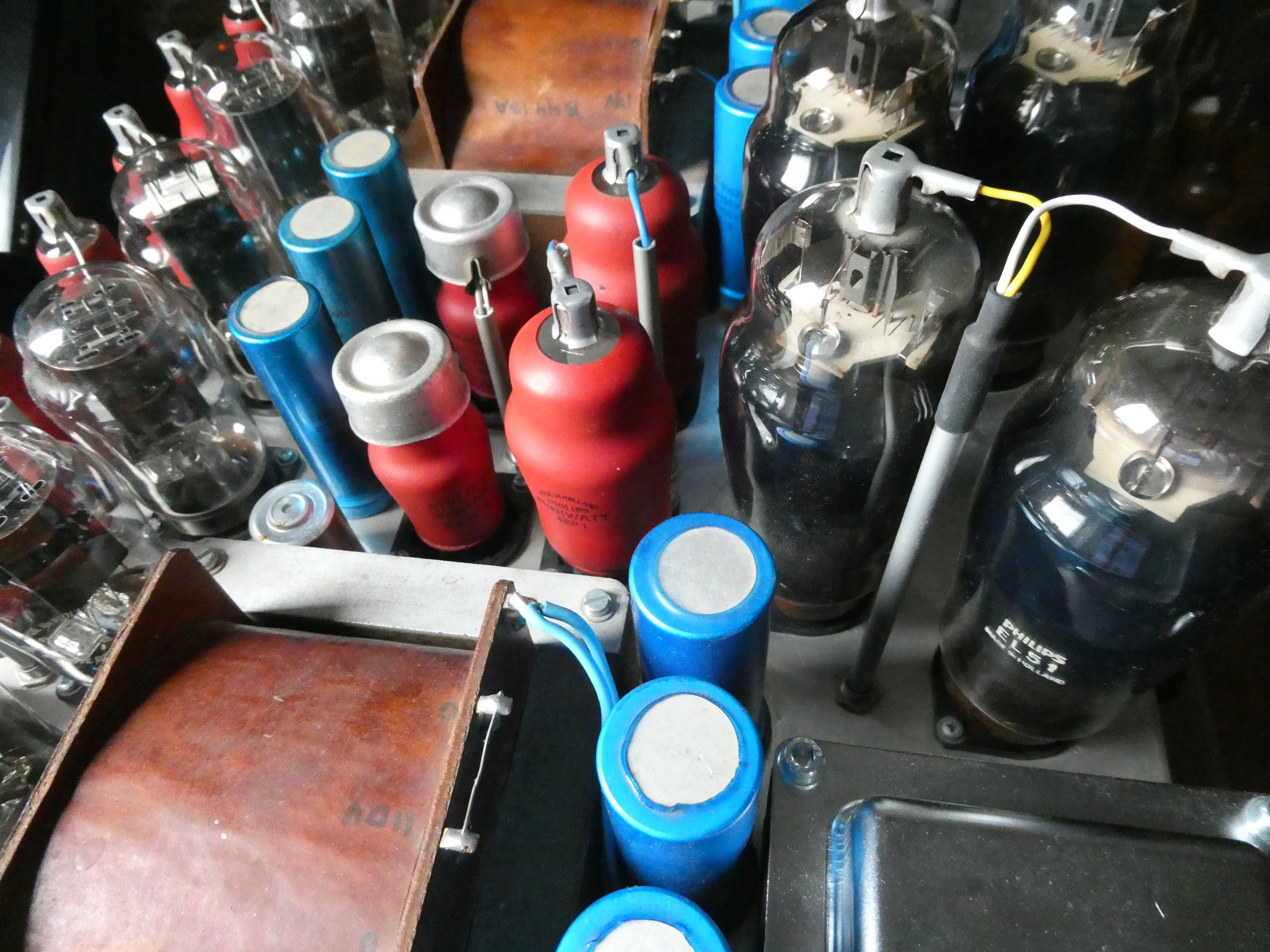
2007-08-24 Here I will report a bit about an amplifier I'm building. It may take a long time because I'm in no hurry to finish it ;-) The main goal is to make an amp with 1930's side contact tubes without any semiconductors. There will be the following tubes: 4x EL51, 7x AZ4, 2x EE1, and the rest EF6 tubes probably. As you can see, the main transformers and the p-sockets are already mounted. For the AZ4's I will add some small transformers at the bottom side, which is still completely empty. |